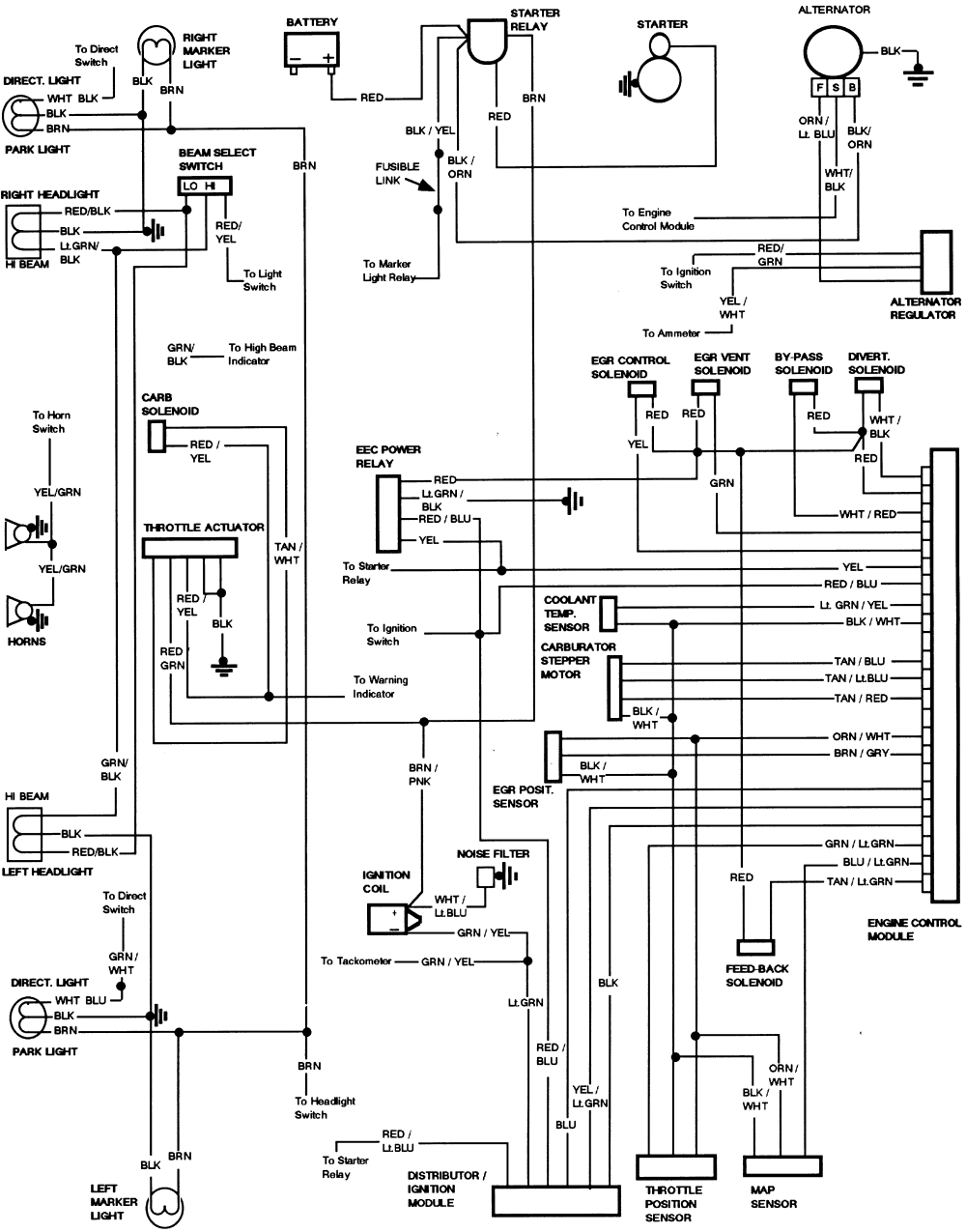
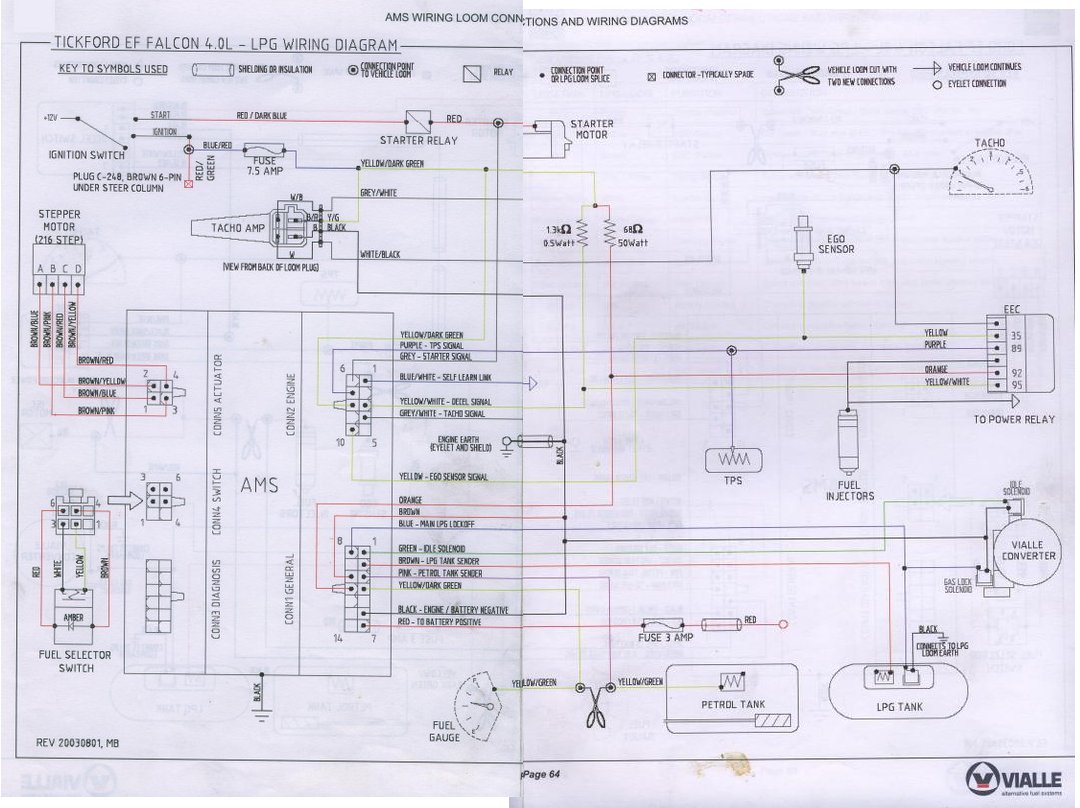
Ford EEC-IV Documents
Ford EEC-IV Connector Pinout
The EEC-IV adapter board kit allows you to install MegaSquirt into virtually any Ford vehicle that uses an EEC-IV computer, without cutting a single wire. Ford used the EEC-IV ECU from 1983 until 1995 in many of their US-market cars, including the 5.0 Mustang, Thunderbird Turbo Coupe, Merkur XR4Ti, pickup trucks, and countless Escorts, Tauruses. Ford EEC-IV Ignition Problem I have a 1986 Thunderbird with a 3.8 liter engine and the EEC-IV System. Recently it - Ford 1986 Thunderbird question.
| EEC-IV Wiring Information | |||
| Pin No | Wire Colour | Purpose | Voltage |
|---|---|---|---|
| 1 | Not Used | ||
| 2 | Not used | ||
| 3 | Not Used | ||
| 4 | Not Used | ||
| 5 | Not Used | ||
| 6 | Not Used | ||
| 7 | Engine Coolant Temp | 20*C-3.1V, 40*C-2.2V, 100*C-0.5V | |
| 8 | Not Used | ||
| 9 | Not Used | ||
| 10 | Airconditioning Clutch On | 0V Aircon Off, 12V Aircon On | |
| 11 | Not Used | ||
| 12 | Not Used | ||
| 13 | Not Used | ||
| 14 | Not Used | ||
| 15 | Not Used | ||
| 16 | Ground | 0V | |
| 17 | Self Test Output (STO) | PWM signal 0V-12V | |
| 18 | Not Used | ||
| 19 | Not Used | ||
| 20 | Case Ground | 0V | |
| 21 | Idle Speed Control | +8V to +11V Engine Running | |
| 22 | Fuel Pump Control | +12V Ignition On | |
| 23 | Knock Sensor (Unleaded Only) | +3V Engine Running | |
| 24 | Not Used | ||
| 25 | Intake Air Temperature Sensor | 0*C 3.9V, 20*C 3,1V, 40*C 2.2V | |
| 26 | Sensor Reference Voltage | +5V | |
| 27 | Air Flow Sensor (Unleaded Only) | Variable Voltage | |
| 28 | Not Used | ||
| 29 | Not Used | ||
| 30 | Transmission Position | Neutral 0V-0.1V, In gear 5Volts | |
| 31 | Canister Purge | 8V-10V with Engine Running | |
| 32 | Not Used | ||
| 33 | EGR Solenoid (Unleaded) | Voltage Pulse @ 1800 RPM | |
| 34 | Data Output Link | PWM Data | |
| 35 | Canister Purge Solenoid (Unleaded) | Voltage Pulse when Engine Running | |
| 35 | EGR Vent Solenoid (leaded) | Voltage Pulse when Engine Running @ 1800RPM | |
| 36 | SPOUT (Spark Output) Ignition | 7V average with Engine Running | |
| 37 | Ignition Power | 12V with Ignition On | |
| 38 | Not Used | ||
| 39 | Not Used | ||
| 40 | Ground | 0Volts | |
| 41 | Not Used | ||
| 42 | Not Used | ||
| 43 | Air Flow Sensor (Leaded Only) | Variable Voltage | |
| 44 | Not Used | ||
| 45 | Not Used | ||
| 46 | Signal Ground | 0Volts | |
| 47 | Throttle Position Sensor | 0.7V closed, 4.5V WOT (Wide Open) | |
| 48 | Self Test Input | 0Volts for Self Test, 12V Normal operation | |
| 49 | Not Used | ||
| 50 | Not Used | ||
| 51 | Not Used | ||
| 52 | EGR Vent Solenoid (Unleaded) | Voltage Pulse @ 1800 RPM | |
| 53 | Not Used | ||
| 54 | EGR Vent Solenoid (leaded) | Voltage Pulse @ 1800 RPM | |
| 55 | Not Used | ||
| 56 | PIP Profile Ignition Pick Up | 0V - 12V on Ignition PIP | |
| 57 | Ignition Power | 0Volts Off, 12V Ignition On | |
| 58 | Fuel Injection Ignition Bank 1,3,5 | PWM On Fuel Injection | |
| 59 | Fuel Injection Ignition Bank 2,4,6 | 0Volts Off, 12V On | |
| 60 | Ground | 0Volts | |
See also


The 1994 4.0L V6 Ford Explorer/Ranger is equipped with the E.E.C IV system and so its computer has 60 pins.
Whether you're tracing down an electrical short or testing one of the input/output components of the PCM, pinout charts come in handy. Below you'll find the description of each pin.
| 1994 4.0L Ford Explorer/Ranger 60 Pin Connector | ||
|---|---|---|
| Pin | Wire Color | Description |
| 1 | YEL | Keep Alive Power (KAPWR) |
| 2 | LT GRN | Brake On-Off (BOO) Switch |
| 3 | GRY/BLK | Vehicle Speed Sensor (VSS) (+) |
| 4 | TAN/YEL | Ignition Diagnostic Monitor (IDM) |
| 5 | -- | Not Used |
| 6 | PNK/ORG | Vehicle Speed Sensor (VSS) (-) |
| 7 | LT GRN/RED | Engine Coolant Temp (ECT) Sensor |
| 8 | DK GRN/YEL | Fuel Pump Monitor (FPM) |
| 9 | PNK/LT BLU | MAF Ground |
| 10 | DK GRN/ORG | A/C Compressor |
| 11 | -- | Not Used |
| 12 | -- | Not Used |
| 13 | -- | Not Used |
| 14 | LT BLU/RED | MAF Signal |
| 15 | TAN/LT BLU | MAF Ground |
| 16 | ORG/RED | Ignition Module Ground |
| 17 | PNK/LT GRN | Check Engine Light (CEL) |
| 18 | -- | Not Used |
| 19 | -- | Not Used |
| 20 | BLK/LT GRN | Case Ground |
| 21 | WHT/LT BLU | Idle Air Control (IAC) Valve |
| 22 | LT BLU/ORG | Fuel Pump Relay Control |
| 23 | -- | Not Used |
| 24 | -- | Not Used |
| 25 | GRY | Intake Air Temp (IAT) Sensor |
| 26 | BRN/WHT | VREF (5 Volt Reference - EGR Position Sensor, TPS, MAP Sensor) |
| 27 | -- | Not Used |
| 28 | TAN/ORG | Data (+) |
| 29 | GRY/LT BLU | O2 Sensor 1 |
| 30 | LT BLU/YEL | Clutch Switch (MT only) Park Neutral Safety Switch (AT only). |
| 31 | GRY/YEL | Canister Purge (CANP) Solenoid |
| 32 | -- | Not Used |
| 33 | -- | Not Used |
| 34 | --- | Not Used |
| 35 | -- | Not Used |
| 36 | PNK | SPOUT |
| 37 | RED | Ignition Battery Power |
| 38 | -- | Not Used |
| 39 | RED/BLK | O2 Sensor 2 |
| 40 | BLK/WHT | PWR Ground |
| 41 | -- | Not Used |
| 42 | -- | Not Used |
| 43 | -- | Not Used |
| 44 | DK GRN | Octane Adjust |
| 45 | -- | Not Used |
| 46 | GRY/RED | Signal Return (Sensor Ground) |
| 47 | GRY/WHT | Throttle Position Sensor (TPS) Signal |
| 48 | WHT/PPL | Self Test Input (STI) |
| 49 | GRY/RED | Ground |
| 50 | -- | Not Used |
| 51 | -- | Not Used |
| 52 | ORG/YEL | Shift Solenoid 3-4 |
| 53 | PPL/YEL | Torque Convertor Clutch Solenoid |
| 54 | PNK/YEL | Air Conditioning |
| 55 | -- | Not Used |
| 56 | GRY/ORG | Profile Ignition Pickup (PIP) |
| 57 | RED | VPWR (From PCM Power Relay) |
| 58 | TAN | Injector Bank 1 |
| 59 | WHT | Injector Bank 2 |
| 60 | BLK/WHT | Power Ground |

Safety Precautions
Here are some very important safety precautions when testing the wires coming out of the 60 pin PCM connector.
Ford Eec Iv Computer Identification
- If one or any of the wires on your Ford pickup DO NOT match the color stated in the pin out charts, then you should not use the pin out charts in this article. Why? Because this is the clearest indication that these ARE NOT the connector pin out charts for your particular Ford 4.0L Explorer or 4.0L Ford Ranger.
- Never probe the front of the connector.
- You should use a wire piercing probe and probe the wire a few inches away from the connector.
- To see what this tool looks like: Wire Piercing Probe.
- You should use a back-probe.
- You should use a wire piercing probe and probe the wire a few inches away from the connector.
- You should never disconnect any of the PCM connectors without first disconnecting the battery negative terminal.
Disclaimer
I've made every effort to double and triple check the above info (and in the next couple of pages) and I've used the best sources to compile it, but nothing in life is perfect. I don't have a staff of proof readers or editors, I'm just a little guy typing this stuff up in my spare time to help and give back to the Do-It-Yourself community. So without further ado, here's my disclaimer:
© copyright Abraham Torres-Arredondo: This information is distributed in the hope that it will be useful, but WITHOUT ANY WARRANTY; without even the implied warranty of MERCHANTABILITY or FITNESS FOR A PARTICULAR PURPOSE.

Ford Eec Iv System
If you do spot errors, please let me know. You can use the contact form at the end of the article.
Ford Eec Iv Schematic
If this info really saved the day, buy me a beer!